PhCNC LSSE
Intended for Windows users who need the documented PhCNC CAM workflow: Gerber, ODB++, Excellon and DXF import; multi-tool isolation and rubout; project arrangement and panelization; native arc output; and CNC simulation.
PCB CAM software converts PCB manufacturing data into machining operations for CNC PCB milling. This comparison focuses on Gerber-to-G-code workflows, Excellon drilling, PCB isolation routing, copper clearing and board cutout for prototype production.
Each ODB++ Bridge uses the CAD system's native ODB++ exporter and automatically hands the resulting PCB data to PhCNC LSSE. Watch the workflow for your CAD system:
EasyEDA refers to Pro Desktop; CADSTAR refers to classic CADSTAR, not eCADSTAR. The OrCAD video demonstrates OrCAD X. Native export dialogs may appear. These are independent TELENET integrations, not CAD-vendor endorsements. Supported versions and installation.
Compare the available operation first, then its tool selection, automation and documented limits.
Review scope: Original FlatCAM 8 documentation and CopperCAM publisher documentation, checked . This is a documentation review, not a hands-on test of every version. PhCNC LSSE descriptions follow TELENET's current product documentation. Not confirmed means a function was not established in this scope, not that it is absent; Limited scope means only the stated subset is documented.
| Feature | PhCNC LSSE | FlatCAM 8 | CopperCAM |
|---|---|---|---|
| Input and PCB data | |||
| Gerber RS-274X import | Yes | Yes | YesIncluding macros and polygon surfaces |
| Excellon drill import | Yes | Yes | Yes |
| ODB++ project import | YesDirectories and supported compressed packages | Not confirmedNot listed among FlatCAM 8 source formats | Not confirmedNot documented in the reviewed publisher pages |
| ODB++ Bridge / automatic CAD-to-CAM import | YesZero Clicks: after starting the Bridge command in your PCB CAD, PhCNC imports the native ODB++ result in CAM mode with no additional import clicks.Eight supported PCB CAD integrations | Not confirmedAn equivalent native ODB++ Bridge workflow is not documented in the reviewed FlatCAM 8 manual | Not confirmedAn equivalent native ODB++ Bridge workflow is not documented in the reviewed publisher page |
| DXF import | YesAutoCAD DXF | Not confirmedThe manual lists SVG import, not DXF | Not confirmedOfficial page confirms DXF output, not import |
| Multiple PCB layers | YesMultiple designs and layers in a project | YesMultiple Gerber objects, including top and bottom layers | YesUp to four circuit layers, plus drill and cutout data |
| PCB CAM operations | |||
| Isolation routing | YesUp to eight isolation tools | Yes | YesSimple or multiple contours |
| Multiple-tool copper removal | YesLarger tools used where geometry permits | Not confirmedTool diameter and multiple isolation passes are documented; automatic multi-tool allocation is not confirmed | YesLarge-tool roughing and engraving-tool corner finishing; not an eight-tool claim |
| Copper clearing / rubout | YesUp to eight rubout tools | YesNon-copper geometry and Paint Area, with tool diameter, overlap and margin | YesHatched copper-removal areas |
| Drilling from PCB data | Yes | Yes | Yes |
| Peck / stepped-depth machining | YesIsolation, rubout, drilling, cutting and masking drill | Limited scopeMulti-Depth / Depth-per-pass cutting documented; peck drilling not confirmed | Not confirmedBoring cycles are documented; peck depth is not confirmed |
| PCB board cutout | YesCompensated internal and external contours | YesRectangular cutouts with holding gaps; tutorial also notes arbitrary shapes | YesAutomatic cut-path with support bridges |
| Panelization | YesCloning and production-panel arrangement | YesShell panelize command: geometry copies in rows/columns with spacing | Not confirmedNot documented in the reviewed publisher pages |
| Alignment / registration workflow | YesRegistration pins, fiducial alignment and dedicated pin-drilling program | YesDouble-sided tool: layer mirroring and symmetric alignment holes | YesAutomatic or manual layer alignment |
| Toolpath, output and workflow | |||
| G-code generation | Yes | Yes | Yes |
| Native G2/G3 arc output | YesDetected circular geometry is preserved as native arcs | Not confirmedNative arc generation not established by the reviewed manual | Not confirmedG-code output alone does not establish native arcs |
| G-code simulation / verification | YesCNC workspace simulation; no machine control | Limited scope2D G-code path display; machining simulation not confirmed | Not confirmedMachining simulation not documented in reviewed pages |
| Tool library / tool assignment | YesSeparate operation tools and parameters | Limited scopeJob tool diameter and Excellon tool selection; persistent tool library not confirmed | YesTool library and drilling strategies |
| Configurable postprocessor output | YesM06 / manual pause, modal output, line numbering, custom header and footer | Limited scopeG-code preamble/postamble and coordinate formatting; full postprocessor system not confirmed | YesFully customizable postprocessor output |
| Project files | YesCreate, combine, save and reopen PhCNC projects | YesSave, Save As, Save a Project Copy and Open Project, including options | YesCurrent project retained in the installation directory |
| Direct CNC machine control | NoPhCNC LSSE provides simulation and verification, not machine control. Other PhCNC editions provide real CNC machine control. | Not confirmedReviewed workflow exports G-code for an external machine controller | NoProduces output for external machine software |
| License model | Commercial perpetual licenseFree, no-time-limit evaluation for preparation and simulation; production-file export requires a license. | Free and open sourceOriginal FlatCAM project; beta/fork distributions are outside this comparison. | Commercial, no time limitNamed license, not tied to a computer; updates within the same major version. Unlicensed export: 25 drills and 25 isolation contours, plus cutout and centering holes. |
Watch real project preparation before trying your own board.
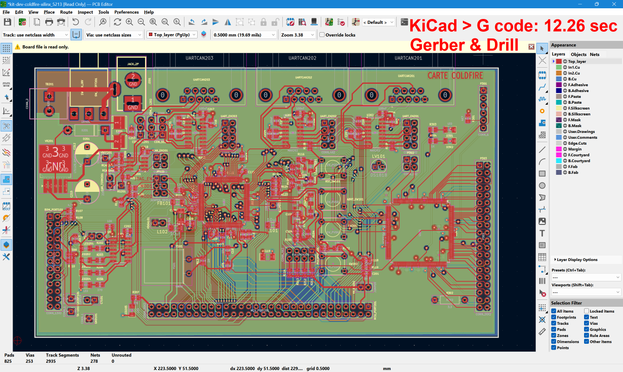
Follow a KiCad Gerber and drill project through import and CAM toolpath generation.
Watch Gerber demonstration →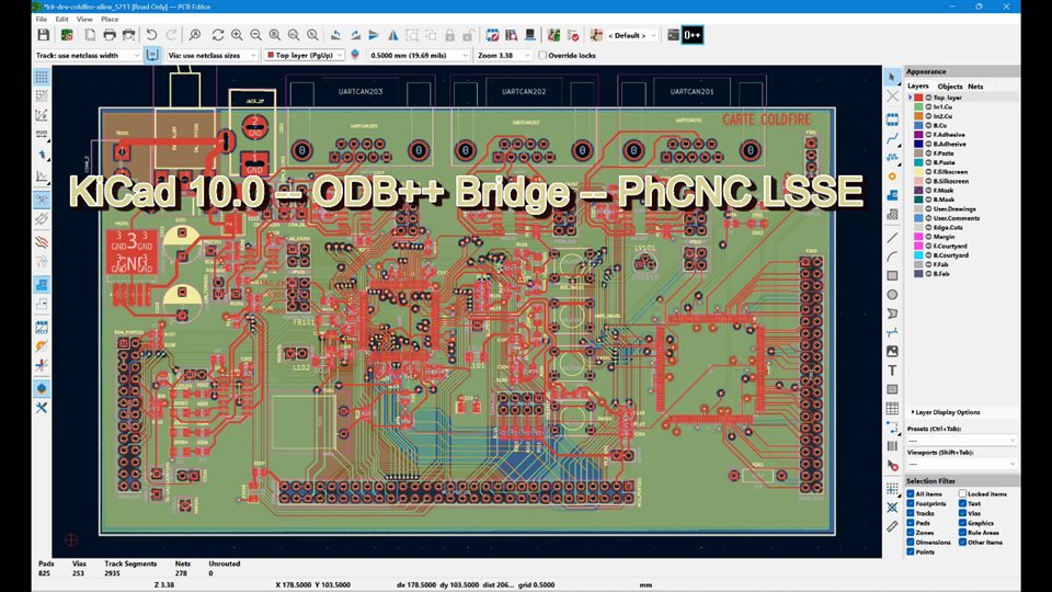
See native ODB++ export and Bridge transfer from the active KiCad board into PhCNC LSSE.
Watch KiCad Bridge demo →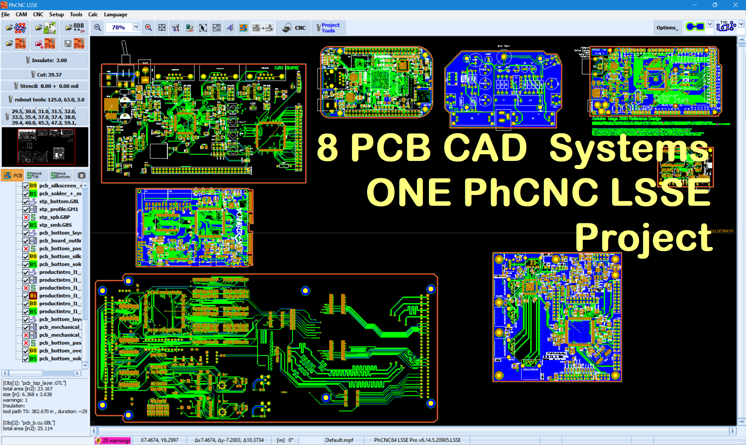
Watch eight native CAD exports, manual board arrangement in one project and Copper View review.
Watch all eight Bridges →CAM benchmark times shown on the Gerber demo are processing measurements, not video durations or milling times. Board arrangement in the combined demonstration is manual; the final Copper View is not physical milling.
Evaluate project preparation, toolpath generation and G-code simulation without a time limit. A valid PhCNC LSSE license is required for production-file export.
Software license: EUR 75. Evaluation and licensing details.
The CAM stage interprets manufacturing geometry, assigns tools and machining parameters, and generates machine-readable output.
Isolation routing removes narrow channels of copper around tracks and pads so electrically separate nets remain isolated. PCB CAM software calculates tool-center paths from the actual Gerber geometry while accounting for the selected cutter diameter.
A typical workflow moves from Gerber copper and outline data to interpreted CAM geometry, then to machining toolpaths and finally G-code. Excellon drill data is processed separately because it describes hole positions and tool diameters rather than copper artwork.

Isolation normally removes only the copper needed to separate conductors. Copper clearing, also called rubout, removes larger unwanted areas. This can require different path strategies and larger tools than fine isolation work.
Dense PCB geometry may require a small cutter, while open regions can be processed with a larger tool. A documented multi-tool strategy can reduce the amount of work assigned to small tools, but the exact behavior differs between products and versions.
Prototype production usually includes Excellon-based drilling and routing of the finished board outline in addition to copper isolation. Tabs or support bridges may be needed to retain the board safely during contour cutting.
Double-sided work requires the bottom layer to be transformed consistently and both sides to share a reliable physical reference. Mirroring, alignment holes, registration points and machine setup all affect whether the second side matches the first.
The appropriate choice depends on input formats, required PCB operations, preferred operating environment and licensing model.
Intended for Windows users who need the documented PhCNC CAM workflow: Gerber, ODB++, Excellon and DXF import; multi-tool isolation and rubout; project arrangement and panelization; native arc output; and CNC simulation.
The original project's manual documents isolation routing, copper-area clearing, drilling, board cutout and saved projects. This column does not describe later beta or fork releases.
Its current official documentation describes a commercial Windows workflow for Gerber/Excellon import, isolation engraving, copper clearing, drilling, board cutout and configurable output for external CNC software.